MINI INVERTER PROJECT CIRCUIT DIAGRAM
Photovoltaic water pump inverter project
We studied a simple and economical approach to design a solar PV powered based DC water pumping which requires limited components, no requirement of batteries and controller. . The simplest type of PV system one could ever design is by connecting single or multiple PV modules directly to the DC load as shown in. . Now before we begin with the design of the system for water pumping it is important to understand some terms which are closely related to design such a standalone system.. . To understand this simply let us take a design example where we need 50 m3water per day from a depth of 20 m. It has elevation, standing water level, and drawdown of 10 m, 10 m, and 4 m respectively. Water density is 1000 kg/m3 and acceleration due. . All the above parameters are very useful for the design of the system for water pumping using solar PV modules. Now let us see how these parameters and different steps can be useful. This paper describes the design and development of a solar photovoltaic (PV) inverter which is used to drive a water pump for irrigation purposes. The inverter output is fed to a three phase ac induction motor which drives the pump. [pdf]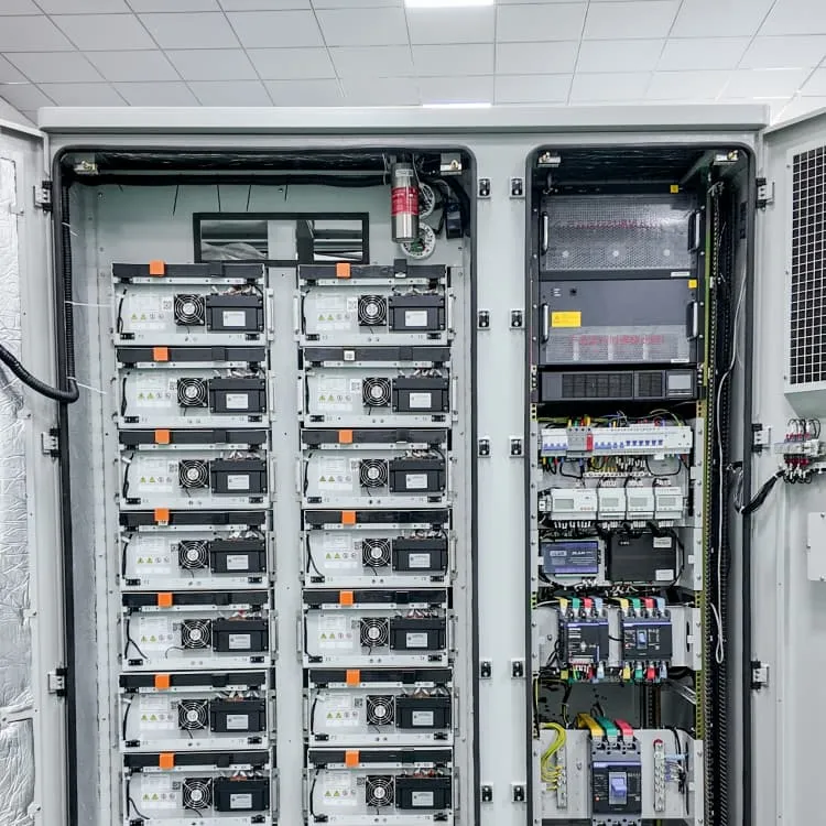
Uganda 5G communication base station inverter construction project Section 1
Due to the widespread installation of Base Stations, the power consumption of cellular communication is increasing rapidly (BSs). Power consumption rises as traffic does, however this scenario varies from ge. [pdf]
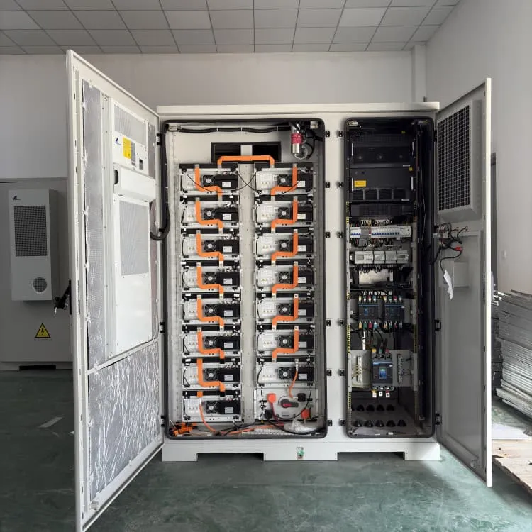
Inverter DC measurement
In this guide, we explain how to test an inverter with a multimeter step by step, focusing on the power input, DC bus voltage, IGBT modules, capacitors, and output terminals. With proper safety precautions, a multimeter becomes a powerful tool for quick fault detection. [pdf]FAQS about Inverter DC measurement
How to calculate inverter voltage?
The inverter voltages eνM with ν = 1, 2, 3, according to the corresponding control signal, can take on the value +Ud /2 with Sν = 1 or the voltage value -Ud /2with Sν = 0. (2.01) To calculate the line voltages in the machine, first the mesh equations are set up: (2.02)
What is the difference between a converter and an inverter?
Since different machines have different frequency and voltage requirements, a circuit known as a converter is used to convert AC current from the power grid to a DC current, and then an inverter is used to convert the DC current to an AC current with the frequency and voltage required by the machinery being driven.
How are currents and voltages measured in a pulse width modulated inverter?
The currents and voltages are measured in all three lines. Despite the pulsed voltage of the pulse width modulated inverter, the current is still approximately sinusoidal. Therefore, the current signal is used to derive the cycle time for mean-value calculation in the power measurement.
What is a pulse width modulated inverter?
Innovative measuring instruments are needed to be able to test and optimize the drive train of an electric vehicle. They must enable both highly accurate power measurements and calculation of various intermediate values. A pulse width modulated inverter converts a DC voltage into an AC voltage with variable frequency and amplitude.
What is an inverter used for?
Inverters can be used to control motor speed in a fine-grained manner by converting DC to AC. They’re used in a variety of settings where they’re needed to drive equipment ranging from electric products to large industrial machinery.
What happens if a pulse width modulated inverter is less than Delta?
If the sine voltage is greater than the delta voltage, a positive voltage is generated. The pulse width modulated inverter switches to a negative voltage if the sinusoidal voltage is less than the delta voltage. The frequency of the triangular voltage is equivalent to the switching frequency at which the power semiconductors switch.