FUNDAMENTALS OF CURRENT AND VOLTAGE CONTROL LOOPS FOR

Photovoltaic panels measure current or voltage
This is a DC power meter (aka watt meter): You can find them for cheap on Amazon. Connect one inline between your solar panel and charge controller and it’ll measure voltage, current, wattage, and more. Here’s how to use one. . Your multimeter is your best friend when testing solar panels. You can use it to check: 1. Open circuit voltage (Voc) 2. Short circuit current (Isc) 3. Current at max power (Imp) Here’s. . A clamp meter, sometimes called an ammeter, can measure the level of current flowing through a wire. You can use one to check whether or not your solar panels are outputting their expected number of amps. A clamp meter makes solar panel testing incredibly quick and. . If your solar panel isn’t outputting as much power as you expect, first do the following: 1. Make sure the panel is in direct sunlight and is facing and angled toward the sun 2. Check that no part of the panel is in shade 3. Clean the solar panel if it’s dirty 4. Make sure there are no. [pdf]
Voltage and current of photovoltaic panel group
Voltage, measured in volts (V), acts like the pressure pushing electrical charges through a circuit, while current, measured in amperes (A), is the flow rate of those charges. For instance, a typical 60-cell PV panel produces around 36 volts and 8-9 amps under full sunlight. [pdf]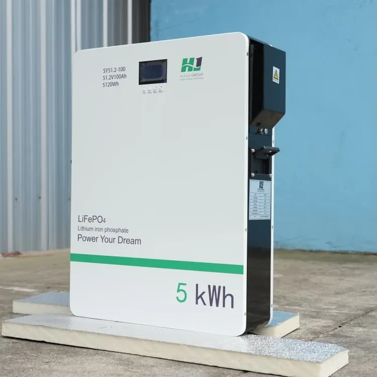
Inverter voltage control configuration
In this paper, we study the optimal structure of voltage controllers for ac inverter systems. In deriving the controller, we present a system-atic design framework for designing multivariable voltage controllers with robust and optimal performance. [pdf]FAQS about Inverter voltage control configuration
What is internal control of inverter?
Internal control of Inverter. In this method of control, an ac voltage controller is connected at the output of the inverter to obtain the required (controlled) output ac voltage. The block diagram representation of this method is shown in the below figure.
What is a control state in an inverter?
Each control state is a combination of the following three fields: AC output power limit – limits the inverter’s output power to a certain percentage of its rated power with the range of 0 to 100 (% of nominal active power). CosPhi – sets the ratio of active to reactive power.
What is a motor control inverter?
In motor control applications, inverters handle the control of circuit voltage along with frequency so that the saturation of motor magnetic circuits is avoided. In the case of variable speed drives, inverters with voltage control help in achieving voltage variation.
How to control AC voltage in an inverter?
Basically, there are three techniques by which the voltage can be controlled in an inverter. They are, Internal control of Inverter. In this method of control, an ac voltage controller is connected at the output of the inverter to obtain the required (controlled) output ac voltage.
What are voltage control techniques for inverters?
This is required to avoid saturation and ensure operation at constant flux density. The Voltage Control Techniques for Inverters can be affected either external to the Inverter Control or within it. The Voltage Control Techniques for Inverters can be done in two ways. (a) The variation of dc link voltage can be achieved in many ways.
Which control modes can control the active output power of the inverter?
Active Power Control The following modes can control the active output power of the inverter: RRCR Active Power Limit Wakeup Gradient P (f) If several control modes are active, the output power of the inverter will be the minimum power.