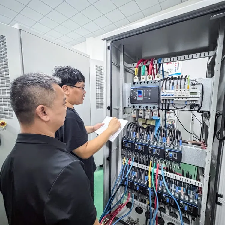
The current of one of the three phases of the inverter is high
Three Phase Inverter | DC-TO-AC INVERTER
Fortunately the torque pulsations due to harmonic currents are of high frequencies and their effect gets subdued due to the large mechanical inertia of the drive system. The motor speed hardly
Three Phase VSI with 120° and 180° Conduction Mode
A three-phase inverter is a type of power electronic device that converts DC (Direct Current) power into AC (Alternating Current) power with three phases.
How does a Three Phase Inverter Work? | inverter
A three-phase inverter circuit is commonly used in high-capacity applications due to constraints related to the capacity of power switching
Solving A VFD Current Imbalance
A commonly observed phenomenon seen by electricians after installing a variable frequency drive (VFD) is a measurable current imbalance on the input to the VFD when
Three Phase VSI with 120° and 180° Conduction Mode
In this conduction mode of three phase inverter, each thyristor conducts for 180°. Thyristor pair in each arm i.e. (T1, T4), (T3, T6) and (T5, T2) are turned on with a time interval of 180°. It
What is Three Phase Inverter and How Does It Work
What is three phase inverter Three phase inverters are power electronics devices used to convert direct current to alternating current and are commonly used in
What is Three Phase Inverter and How Does It Work
After discussing the split-phase inverter, today we will analyze a key component in large solar installations: the three-phase inverter. The departure
Three-Phase Inverters
According to Figure 23, the current in each inverter arm is delayed to reach its basic voltage. Because current is inductive by nature, it does not change quickly when the voltage polarity is

CHAPTER4
In order to realize the three-phase output from a circuit employing dc as. the input voltage a three-phase inverter has to be used. The inverter is build of. gives the required output. In this

Three Phase Inverter Circuit Diagram
In the graph, we can see that three voltage waveforms are out of phase with each other by 120º. In this article, we will discuss the 3 phase inverter working principle, which is
Three-Phase Inverter Design | Tutorials on Electronics | Next
In contrast to VSI, the Current Source Inverter (CSI) uses a constant DC current source and regulates output current rather than voltage. This topology is advantageous in high-power

Comparison of Inverter Topologies for High-Speed Motor
Abstract—This article investigates and compares the perfor-mance of three-phase inverters against sets of single-phase full-bridge inverters in motor drive applications. Comparisons are
Lecture 23: Three-Phase Inverters
Considering inverter states in which one switch in each half-bridge is always on (for current continuity at the load) there are 23 = 8 switch state possibilities for the 3-phase inverter. We
Model predictive current control for two-phase switches clamping
However, the drawbacks of widespread current harmonic, high switching loss and heavy computational burden are fully exposed. In this article, three-phase voltage source
Three Phase Inverter | Methods of Voltage Control of
The Three Phase Inverter uses PWM for voltage control and hence is called a PWM inverter or constant voltage inverter (Fig. 3.93). In Three Phase Inverter
How does a Three Phase Inverter Work? | inverter
A three-phase inverter circuit is commonly used in high-capacity applications due to constraints related to the capacity of power switching devices, neutral line current, grid load
Three Phase Inverter : Circuit, Working and Its
Generally, the three arms of this inverter will be delayed with 120 degrees angle to generate a 3 phase AC supply. The switches used in the inverter have 50%

3 phases inverter output current
Inverters are generally variable voltage and frequency so at low loads, when output voltage is well below line voltage, you can see a higher output current than line current. There
Three Phase Inverter : Circuit, Working and Its Applications
Generally, the three arms of this inverter will be delayed with 120 degrees angle to generate a 3 phase AC supply. The switches used in the inverter have 50% of ratio and switching can be
Three Phase Inverter Circuit Diagram
The Hybrid Multilevel Inverter is a three-phase inverter specially designed for industrial applications with medium voltage and high power demands. It uniquely combines
Three Phase VSI with 120° and 180° Conduction Mode
In this conduction mode of three phase inverter, each thyristor conducts for 180°. Thyristor pair in each arm i.e. (T1, T4), (T3, T6) and (T5, T2) are turned on

CHAPTER 2
A standard single-phase voltage or current source inverter can be in the half- bridge or full-bridge configuration. The single-phase units can be joined to have three-phase or multiphase
6 FAQs about [The current of one of the three phases of the inverter is high]
What is a 3 phase voltage source inverter?
Three Phase 180° Mode Voltage Source Inverter In this conduction mode of three phase inverter, each thyristor conducts for 180°. Thyristor pair in each arm i.e. (T1, T4), (T3, T6) and (T5, T2) are turned on with a time interval of 180°. It means that T1 remains on for 180° and T4 conducts for the next 180° of a cycle.
What is 180 degree conduction mode in a 3 phase inverter?
In the 180-degree conduction mode, the driven conduction time of each three phase inverter circuit is precisely 180° of the fundamental period. Hence, better voltage utilisation is offered under a three-phase inverter output voltage. Maximum voltage utilisation from a DC source. Maximum fundamental voltage output. High power transfer capability.
How does a DC power source work in a three-phase inverter?
The DC power source of the three-phase current-type inverter, i.e., the DC current source, is achieved through a variable voltage source using current feedback control. However, employing only current feedback cannot reduce the power ripple in the inverter input voltage caused by switch actions, resulting in current fluctuations.
How a 3 phase inverter circuit works?
So here we will discuss the working of an ideal three-phase converter circuit, neglecting all the issues related to a practical 3 phase inverter. A 3 phase inverter circuit diagram converts DC voltage into balanced three-phase AC supply using six switching devices. What is a Three Phase Inverter?
What is a three-phase current-type inverter?
Similar to the three-phase voltage-type inverter circuit, the three-phase current-type inverter consists of three sets of upper and lower pairs of power switching elements. However, the switching method is different from the voltage-type. The inclusion of a large inductance L in series with the DC input minimizes fluctuations in the DC current.
Can a three phase square wave inverter produce balanced AC voltages?
The three-phase square wave inverter as described above can be used to generate balanced three-phase ac voltages of desired (fundamental) frequency. However harmonic voltages of 5th, 7th and other non-triplen odd multiples of fundamental frequency distort the output voltage.
Related information
- North Korea s lithium energy storage power supply custom-made enterprise
- Monocrystalline bifacial 445w photovoltaic module
- Solar water pump inverter always needs voltage regulation
- Timor-Leste BMS battery management system components
- Liquid-cooled 5mwh energy storage cabin
- Samoan companies producing energy storage containers
- Albania s home wind power system
- 590 latest price of photovoltaic panels
- Air Cooling Cabinet Photovoltaic Energy Storage Cabinet Price
- How much electricity can 2 kilowatts of solar energy generate
- Smart inverter 18v to 220v
- Energy storage power station revenue in North America
- Huawei Maldives Home Energy Storage
- Flywheel energy storage electric system
- How many watts of solar energy can be connected in series
- Flexible photovoltaic panels installed on solar panels
- Energy storage battery equipment manufacturers
- 18V 2 5W solar panel
- How many communication base station inverters are there in Mexico
- Do off-grid inverters need energy storage
- Czech mobile outdoor battery cabinet BESS
- High voltage lithium battery pack 72 volts
- 12v 90ah with inverter